Welcome to Micronator
Micronator is a microcontroller system, complete and ready to go out of the web (box).
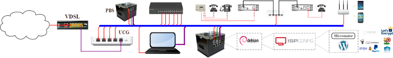
I f you want an idea of what Micronator is or can be, have a look at our Overview. You want a look inside, just click here Inside or here without casing . You prefer the outside of it with its card reader and little RF antenna Ready to go.
The USER MANUAL and the BASIC-11 MANUAL are available. There are some app notes also AN-102 and AN-103. We hope you will enjoy your visit.
Some of the highlights of Micronator
- Fully supported by the community
- All schematics are available
- No jumper to set up. PNP
- A standard « Buffalo » monitor and extensive documentation to allow for easy creation of extended functionality through plugable modules.
Micronator has a very active developer and support community at:
https://www.micronator.org.
We hope you will enjoy using Micronator.
Your Micronator development team
VERSION-6.00 SCHEMATIC
The dev-team just released the schematic for version 6.0, V-600 (PDF 39295bytes) Please note that this schematic is preliminary.
Some of the changes of V-6.00:
- The CPU is F1 (PLCC68):
- Almost same pin-out,
- $Cheaper than the A1
- 8 more I/O bits,
- Data is non-multiplexed, no demux chip
- 1KB RAM internal, no need for external RAM
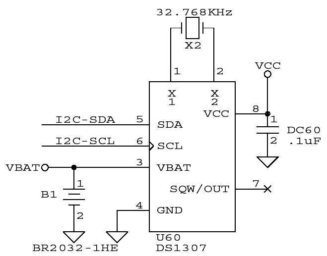
The RTC is DS1307 with battery: BR2032-1HE:
- No caps for the crystal
- DIP 8 pins
- I2C, same as the serial EEPROM 24LC256-I/P
Your Micronator development team
SERIAL EEPROM
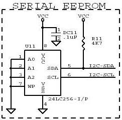 The dev-team is analysing the serial EEPROM.
Introduced in version 6.0 the serial EEPROM is a 32KB x 8 bits non-volatile memory with I2C communication capabilities.
This serial memory is so cheap and since it is using I2C protocol it means that its total cost in terms of $ and PCB real estate is almost nothing.
Since we are already using another I2C chip, the RTC, it won’t require any I/O pins from the CPU.
It mainly gives great opportunities to learn I2C communication and non-volatile memory theories and designs.
Have a look here to see the serial EEPROM schematic block.
Your Micronator development team
The real time clock (RTC)
 The dev-team is analysing the RTC.
When Micronator evolved from version 5.0 to version 6.0, the dev-team decided to change the RTC mainly because it is not Y2K compatible and it is an obsolete chip.
The dev-team choose the DS1307 for:
- its popularity
- price
- great opportunities to learn I2C communication
- direct connection with a low cost battery
- no need for crystal capcitors
- availability
- small footprint in term of PCB real estate
- etc…
Have a look here to see the RTC schematic block.
Your Micronator development team
The address decoder
|
|
|
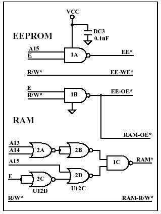
The dev-team is analysing the address decoder.
When Micronator evolved from version 4.04 to version 5.0, the dev-team had already decided to go with another way than the PALCE22V10.
The main reason was the programming of such a device, you need a real universal device programmer for that kind of stuff.
The solution was to try the ispGAL (in system programming) from Lattice Semiconductor. In this familly Lattice has a 22V10 and a gadget that you plug into the parallel port of a PC to program those ispGAL. Also Lattice Semi offer a tutorial and a free downloadable software to generate the « jed » file.
Have a look under Wire Wrap Area on the left hand side column of this web page for the « Prgmr complete kit » to see a wire wrap model of such a device programmer. It worked flawlessly to program the version 5.00 of the address decoder.
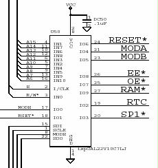
Have a look here to see a better look at the new ispGAL address decoder.
Please note at the lower left side of the ispGAL:
- the pins to in-circuit program the ispGAL: SDI, SDO, SCLK, and MODE.
- the RTC chip select pin is not needed anymore in version 6.00 as we use I2C-SDA & I2C-SCL to communicate with the RTC.
- SP1*, spare-1, is not really needed as it is only used for the user ww area on the CPU board.
Your Micronator development team
THE CRYSTAL
 The dev-team is analysing the crystal circuit.
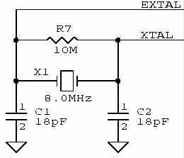
The crystal used in previous version has always been 4.9152MHz. This frequency was used mainly because it was easily divided by a whole number to give a RS-232 baud rate. For version V6.0 the dev-team decided to go with a 8.0 MHz crystal mainly to gain some speed.
For our V6.0 prototype, we will start by using a 4.9152MHz to be able to check the hardware design.
When the hardware will be fully functionnal we will change the crystal to 8.0MHz. The reason to proceed that way is to change only one variable at a time.
Since all the MONITEUR softwares are using 4.9152MHz it will be difficult to start right away with the 8.0 MHz crystal.
The main software to adjust will be the bootstrap programm which is responsible to get all other programs to memory.
Have a look here to get a better view of the crystal schematic block.
Your Micronator development team
The voltage regulator
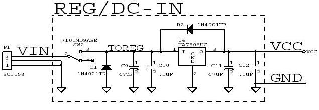 Have a look here to have a better image of the input voltage regulator.
The dev-team is analysing the input voltage regulator.
- In all the previous versions the 7805 was used to regulate the DC input voltage. This regulator was choosen mainly for its availabilty, capacity, package, and price.
- The ON/OFF switch SW2 will be changed for a very small sliding one.
- The DC input connector will be changed to a more standard one. It will be a 5.5 x 2.1mm or a 5.5 x 2.5mm barrel connector which is more common today. Only 2 wires are used with those connectors. A bit more research is needed to find out if 2.1mm is more popular than 2.5mm and if negative center is better than positive. The later choice will reflect the popularity of the wall-mounted power supply ouput connector.
As always, constructive comments are appreciated.
Your Micronator development team
Magnetic card reader
 The dev-team is analysing the MAG-CARD reader.
The MAG-CARD reader was introduced in version 4.04 and was implemented on the RF module. Since that module was using a CIA for the I/O and had a lot of spare pins there was no need to worry about using a few of them.
- In version 6.00, the user might not use the RF module and still want to use the MAG-CARD reader.
- The main question is which pins to use for the MAG-CARD reader?
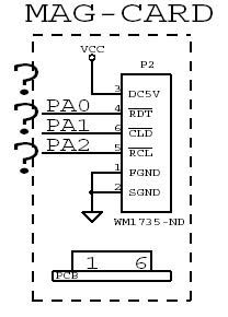
- For the time been the dev-team decided to use the port A pins but not necessarly: 0, 1, or 2.
The price of this connector is around $0.50 and it is the only hardware needed to integrate the MAG-CARD reader into your design. The traces will be on the PCB in case you want to use the MAG-CARD. If you don’t want to use the reader then just don’t put the connector on the PCB and use the I/O pins for something else.
Have a look here to see the MAG-CARD reader schematic block.
Your Micronator development team
Micronator to PC communication
 The dev-team is analysing Micronator to PC communication.
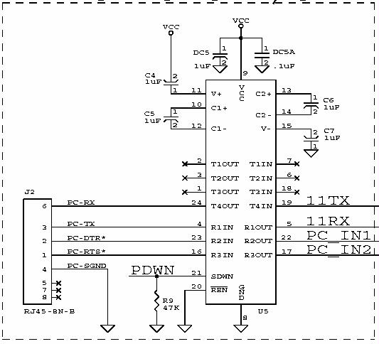
Have a look here to get a better image of Micronator to PC communication schematic block.
In all the previous versions the MAXIM MAX236CNG was the RS-232 compatible chip used to communicate with a PC. It is true that this chip is expensive but it solves so many problems such as PCB real estate, number of needed capacitors and most of all the number of receiver channels.
The dev-team really tried to find a good replacement but never succeeded.
The main feature is the number of receivers. Micronator needs abolutely 3 receivers: one for the RX DATA from the PC, one for the MODE pins of the CPU, and finally one for the RESET.
As always, constructive comments are appreciated.
Your Micronator development team
GERBER FILES in jpeg format
The doc-team just released the gerber files of Version: 4.04:
- Components side. the layer 1 traces 272760 bytes
- Layer 1 cupper the layer 2 traces 294735 bytes
- Layer 2 cupper the layer 1 solder mask 288065 bytes
- Layer 1 solder mask. the layer 1 solder mask 199073 bytes
- Layer 2 solder mask. the layer 2 solder mask 202759 bytes
Your Micronator documentation team
Work in progress by the doc-team
The doc-team has started to produce the wire-wrap user interface tutorial. To see the work in progress USER INTERFACE.
Micronator documentation team